This is a Chemistry lab designed to illustrate the process of electrolysis, defined as chemical decomposition produced by passing an electric current through a liquid or solution containing ions.
Theory:![]()
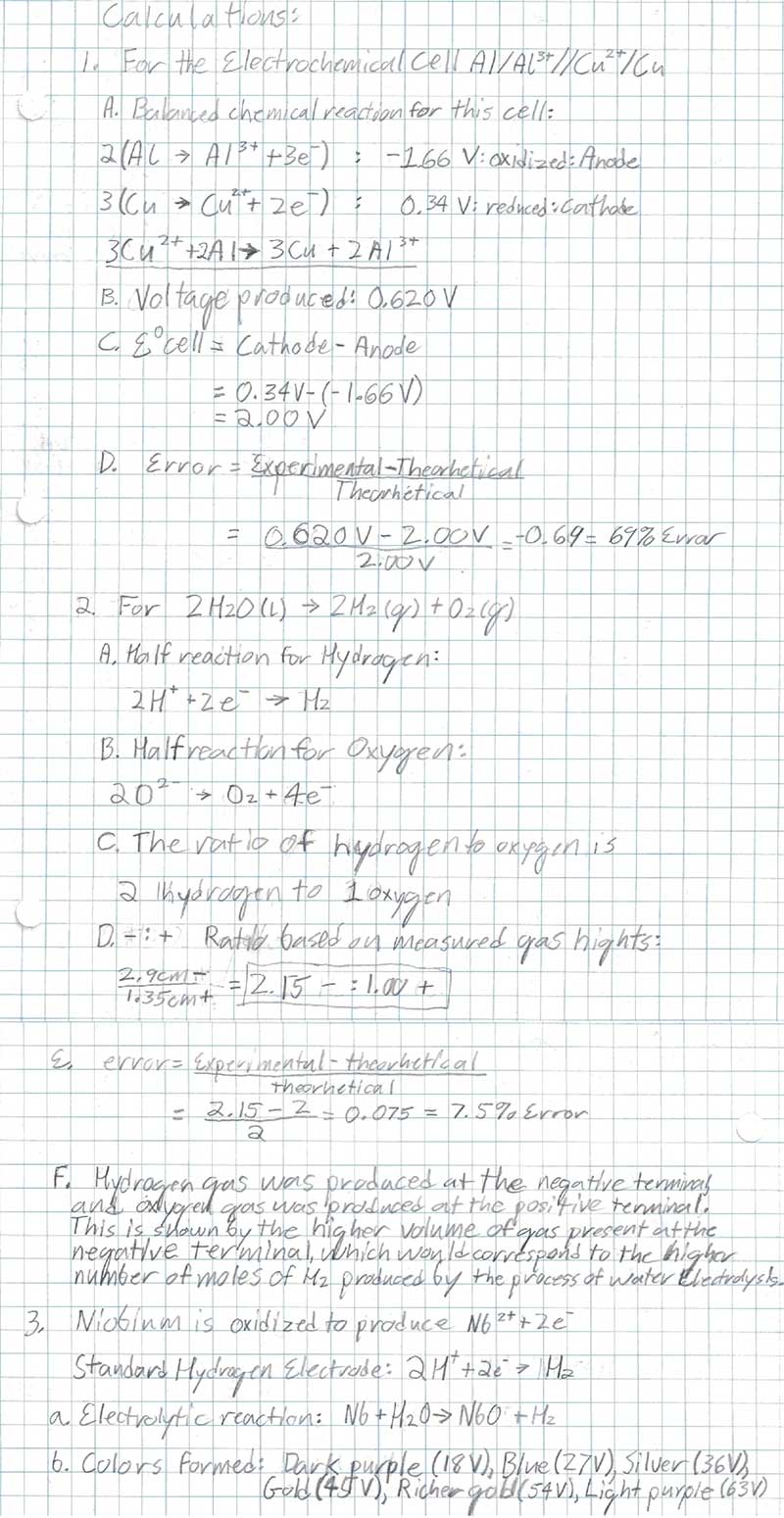
The first experiment involved the creation of a galvanic cell out of an aluminum can and scraps of copper wire, which was used as an energy source to power various small electronic devices. A galvanic cell is an electrochemical cell that is produced by a spontaneous redox reaction. In this case, the spontaneous reaction is between aluminum, the reducing agent, and copper, the oxidizing agent.
This reaction is represented by:
2Al (s) + 3Cu2+ (aq) → 2Al3+ (aq) + 3Cu (s)
In the second experiment, a 9V battery was used to break down water, a reaction represented by the equation:
2H2O (l) → 2H2 (g) + O2 (g)
This is an example of an electrolytic cell, which is non-spontaneous and must have an energy cell connected for the reaction to proceed. In this case, H2 is produced at the negatively charged cathode, and O2 is produced at the positively charged anode at a ratio of two H2 to one O2.
In the third experiment, a series of 9V batteries were connected and used to oxidize a niobium wire in an aqueous borax solution and to cause assorted colors to generate as niobium was converted into niobium oxide. As voltage increased, the thickness of the NbO layer increased, altering reflected wavelengths of light. This leads to the perception of different colors as each battery was added. This is another example of an electrolytic cell.
Summary of Procedure:
 For the first experiment, the bottom of an aluminum can was removed, and the can was placed in a warm nitric acid solution to remove any plastic coatings. A copper wire was placed in a 600 mL beaker with the wire extending from the beaker. Next, a solution of 1 mL of 1 M sulfuric acid and 200 mL of 1 M copper II sulfate was poured into the 600 mL beaker. The aluminum can was wrapped in a sheet of bond paper, which was secured around the can with rubber bands. This wrapped can was placed bottom-down in the 600 mL beaker and 200 mL of a 0.1 M sodium hydroxide in 1 M potassium chloride solution was poured into the can. A voltmeter was used to record the voltage between the two electrodes and the constructed battery was used to power small a buzzer and motor. The voltage was measured before and after a 20-minute interval.
In the second experiment, a crystallizing dish was filled with 250 mL of 1% sodium sulfate solution and several drops of universal indicator. Two test tubes with side arms were attached to ring stand poles. The sidearms were covered with medicine dropper tops, which were pierced through with platinum wires. The test tubes were filled with the same sodium sulfate and universal indicator solution, capped, and placed with the top submerged in the dish solution. The test tube caps were removed, and the platinum wires were connected to the positive and negative terminals of three 9V batteries. The current was allowed to flow for 20 minutes. Finally, the connection was terminated, with the color of solution and volume of gas in each test tube recorded.

In the third experiment, a beaker containing an aqueous borax solution, a plastic mesh, and a stainless-steel wire strip was obtained. A 3-4-inch-long niobium wire was obtained and cleaned to remove fingerprints. Two 9V batteries were then connected in a series. The niobium wire was connected to the positive terminal, and the stainless steel was connected to the negative terminal. The niobium wire was then dipped into the solution for 30 seconds to allow a layer of niobium oxide to form. After this, the wire was removed and wiped off. Another battery was added, and the niobium was dipped into the solution for another 30 seconds. This process was repeated for voltages 18 through 63 at 9V increments. The observed colors at each increment were noted and recorded.
Data:
| Initial Observations of Al can/copper wire battery: Dirty copper wire, clean and shiny on top, copper color, dirty part is whitish green. Initial voltage: 0.662 V |
|
Observations of Al can/copper wire battery after 20 minutes: Looks the same, Cu wire, turned pink under solution. 0.620 V. Bubbly pinkish brown stuff formed on submerged part of the can. Submerged can is very thin and fragile. Wire is significantly cleaner. |
Part 2:
Observations of tube connected to + battery side (anode):
|
Observations of tube connected to - battery side (cathode):
|
Part 3:
Observations after applying various voltages:
| Voltage (V) | Color |
| 18 | Dark Purple |
| 27 | Blue |
| 36 | Silver |
| 45 | Gold |
| 54 | Richer Gold |
| 63 | Light Purple |
Calculations
Interpretation of Results:
The purpose of experiment 1 was to create a functioning battery using an aluminum can and copper wire. This was done successfully, and a voltage of 0.620V was measured using a voltmeter. This voltage was much less than the expected value of 2.00V, which was determined through calculation of standard cell potential equation: E°cell = E°cathode – E°anode. The total error between the measured and expected voltage is 69%.
The second experiment was meant to measure the volumes of gas generated at the anode and cathode of a system by the electrolysis of water, and to determine what molecules are present at each point. To this end, a theoretical hydrogen to oxygen ratio of 2:1 was calculated based on the balanced equation. However, the measured gas volume ratio was 2.15:1. This ratio was only 7.5% different from the expected value. Given the similarities between the two ratios, it can be determined that hydrogen gas had been generated at the anode and that oxygen gas had been generated at the cathode. This is corroborated by the color of the aqueous solution at each cathode. If hydrogen gas is generated at the cathode, it is to be expected that the aqueous solution would have a lower proton concentration, and thus, would have the bluer color associated with a higher pH. Similarly, if oxygen gas is generated at the anode, it would be expected that the aqueous solution be left with a higher proton concentration, and thus have the redder color associated with a low pH.
The third experiment demonstrates the effect of different voltages on the electrolytic oxidation on niobium wire. This reaction can be described by the equation:
Nb + H2O → NbO + H2
Increasing the voltage at the anode resulted in thicker layers of NbO being formed. This is evident from the color of reflected light for each voltage level. As the thickness of the NbO layer increased, different wavelengths of light were cancelled by light interference effects, resulting in changes in the perceived color of the surface.
Sources of Error:
There appears to be a great deal of error in the first experiment, evidenced by the 69% difference between the expected and experimental E°cell values. After the construction of the battery, the copper wire touched the aluminum can, shorting out the battery for around a minute. This may be a contributing factor in the unexpectedly low battery voltage. Additionally, the theoretical E°cell value presupposes a temperature of 298 K. The temperature was not measured during the experiment, but it is unlikely that the temperature was at the theoretical level. This may have led to a lower reduction potential. Another possible source of error could have been in the accuracy of the voltmeter used. It was not calibrated against a known source.
There was only 7.5% error associated with the gas volumes in the second experiment. This was likely due to unequal amounts of excess air remaining in the test tubes after the sodium sulfate solution had been added. The excess air likely remained in the test tubes after the water electrolysis had begun and was counted as part of the H2 and O2 volumes. The inaccuracy of using a ruler to measure gas height could also account for the error.